Changing The MBX Bucker Rolls
Mobius MBX Bucker
Changing The Rolls
Replacing the Rolls and Aligning the Chipper for the MBX Bucker
Step by Step
The Following Tools You'll Need to Replace the Rolls in the MBX Bucker
01

2 New rollers / User guide
02

Some sort of prybar - Can be plastic or wood / Flat screwdriver
03

9/16" Wrench / 9/16" Socket or Ratchet
04

Circlip pliers / 5 Hex wrench - 1/4" - 3/16" - 5/32" - 1/8" - 3/32" / Blue loctite
Removing The Rollers
01
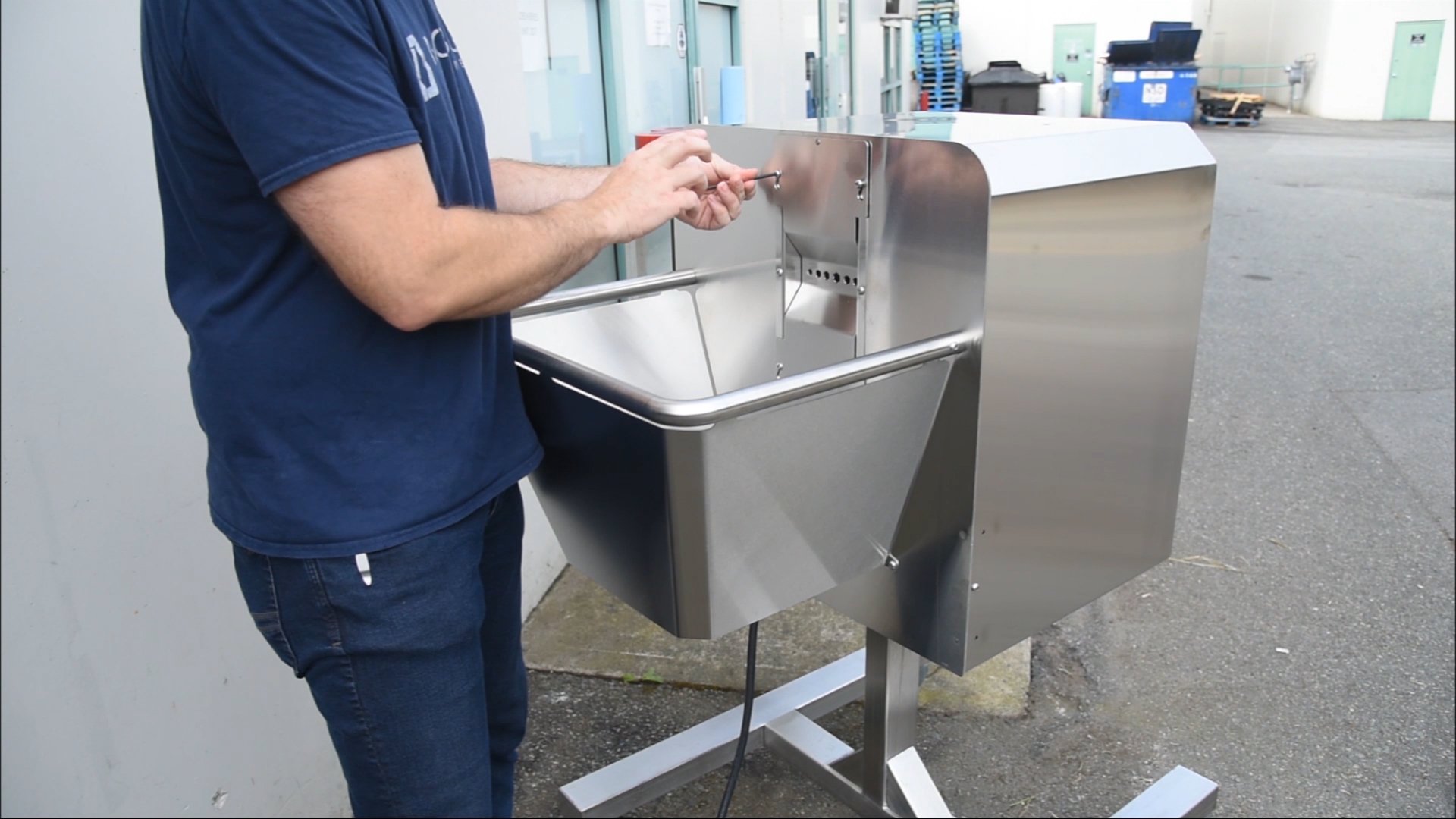
Start by removing the guards and the dieplate. The stem hole dieplate can be removed with the 5/32" allen wrench. Loosen the 4 screws retaining the dieplate and set aside.
02
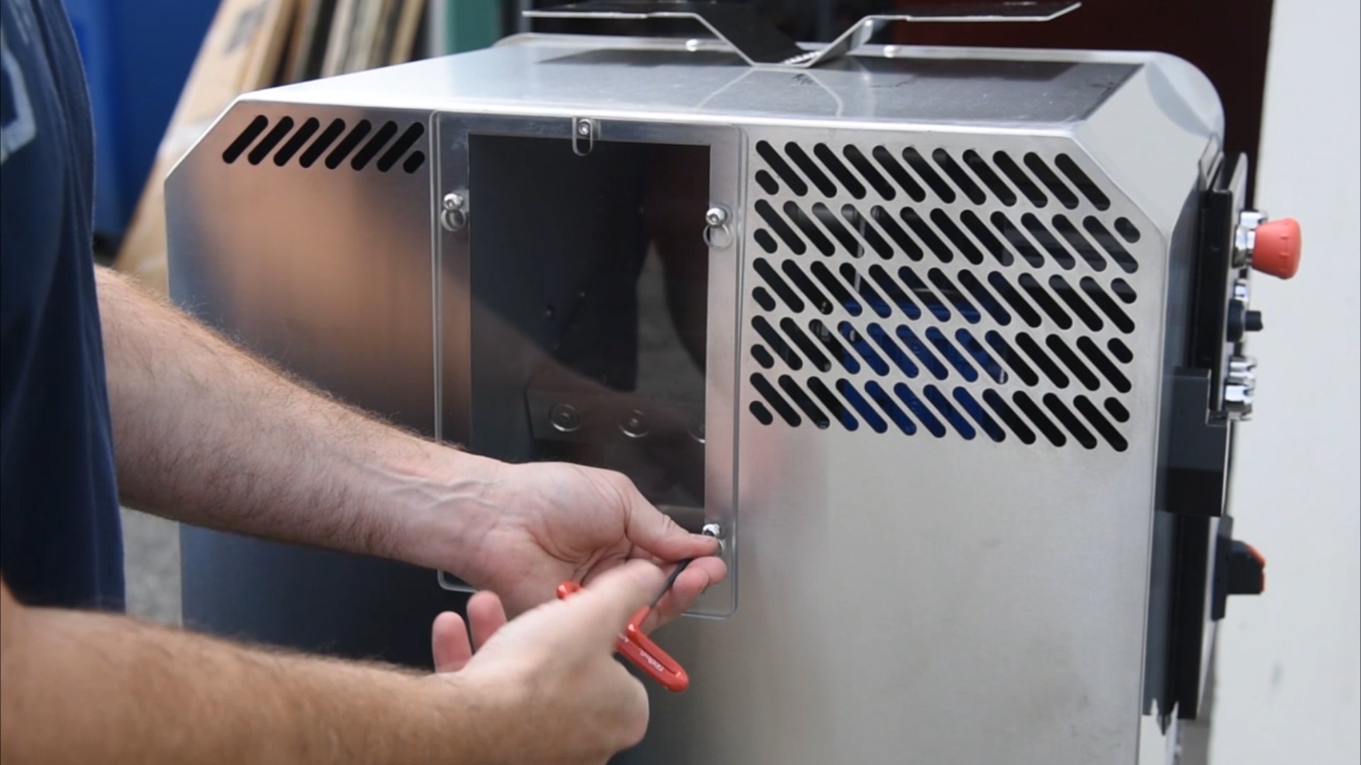
Using the same 5/32" allen wrench, remove the cover over the chipper and set aside.
03
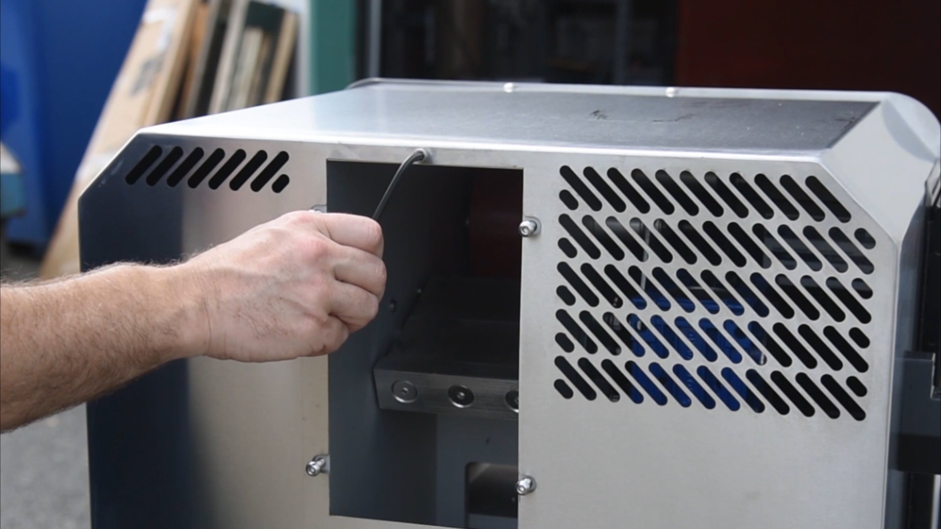
Remove the centre screw with the 3/16" allen wrench, and the 2 button-head screws at the bottom of both side panels.
04
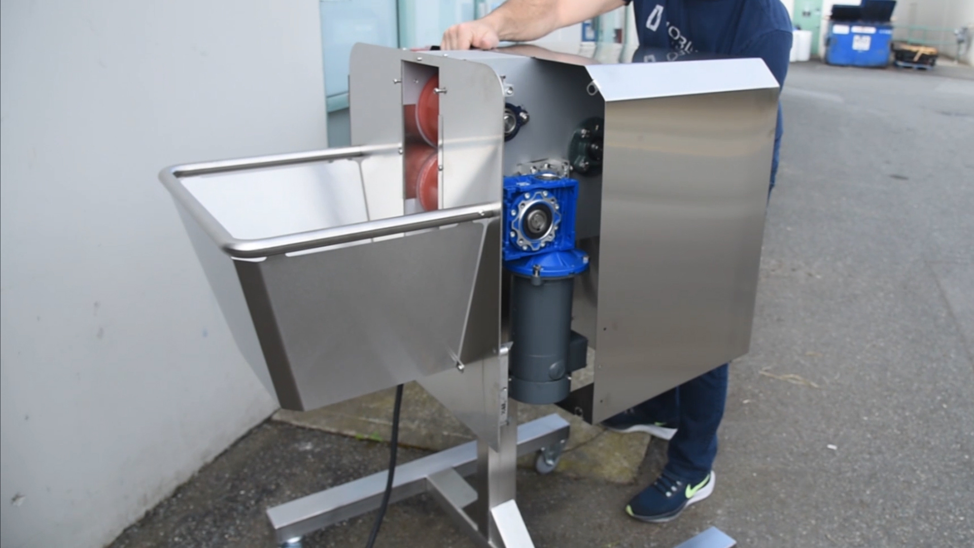
To release the cover, pull down on the shrouding at the bottom, then pull off and release. Repeat on the opposite side, then slide the cover off the MBX.
05
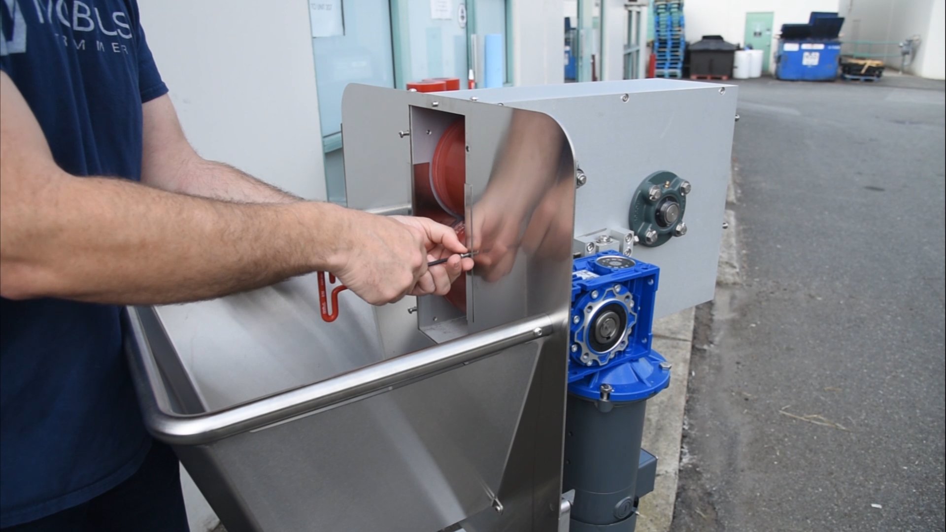
To remove the side plate, use the 5/32" to unscrew the 3 screws on the right side of the rollers.
06
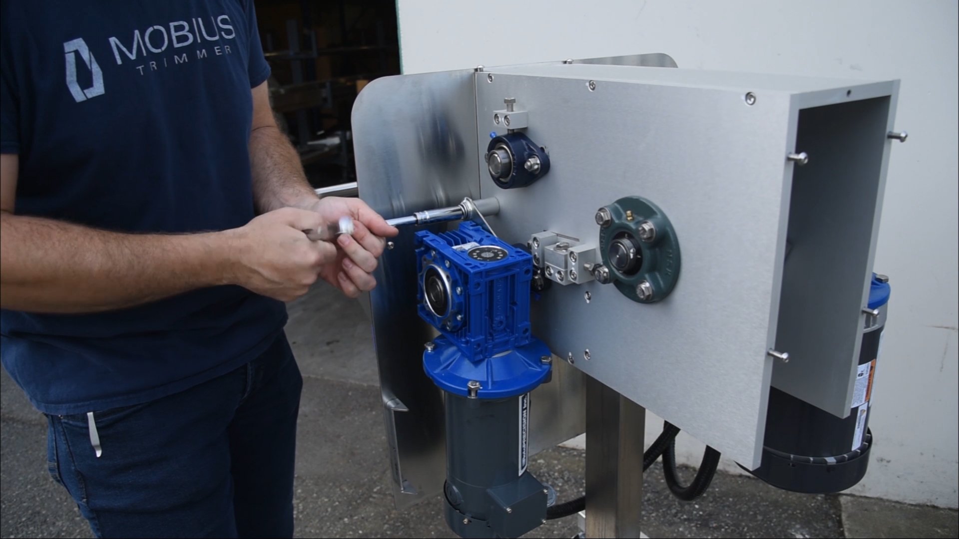
Next, remove the motor with the gearbox using the 9/16" socket. Be careful not to lose any of the parts – there’s an aluminum spacer, and a bolt with 2 washers.
07
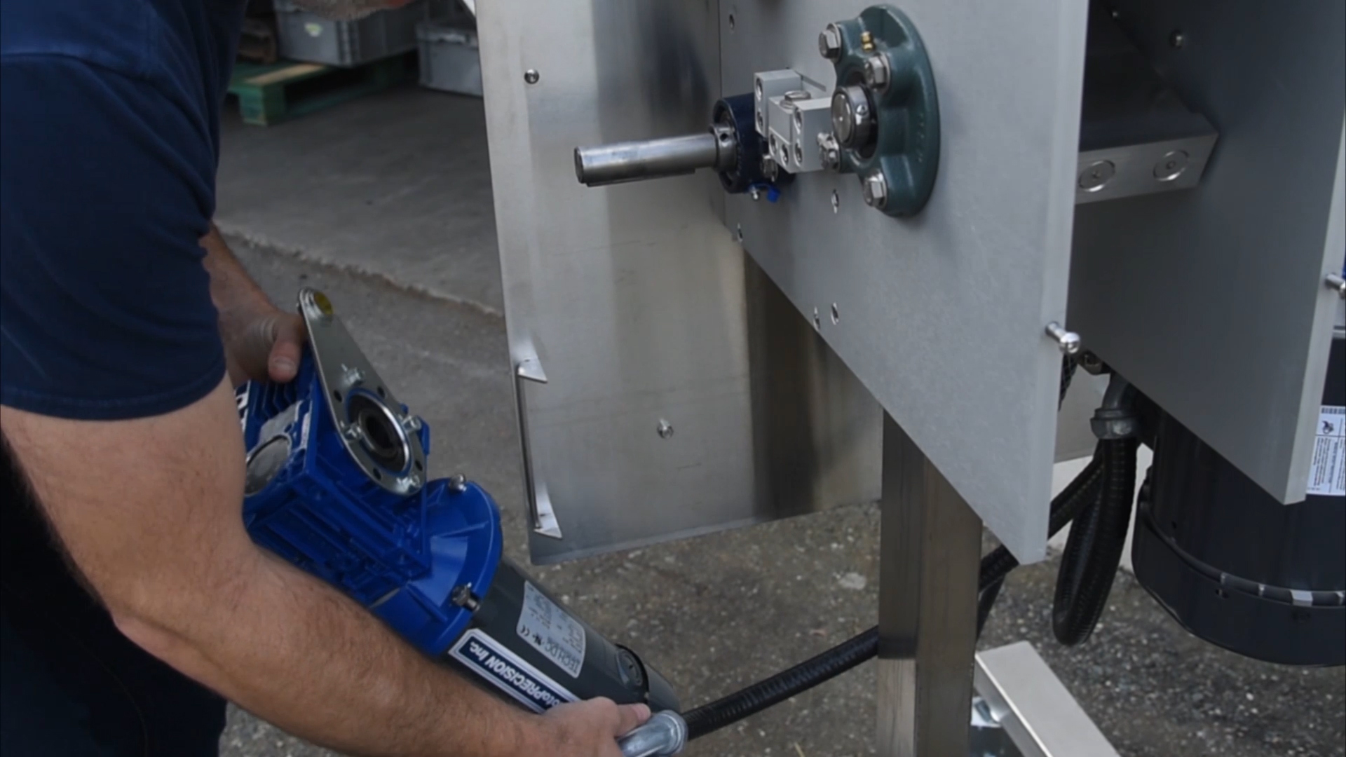
There should be enough slack on the wire that you can set the assembly on the frame. Remove the key sitting in the keyway.
08
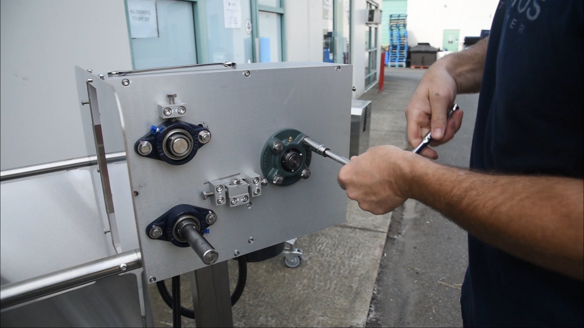
Remove the 4-bolt flange bearing for the chipper using the 9/16" socket on each of the 4 bolts. Note that the grease fitting is at the top – this is where you’ll want it when you put the flange back on.
09
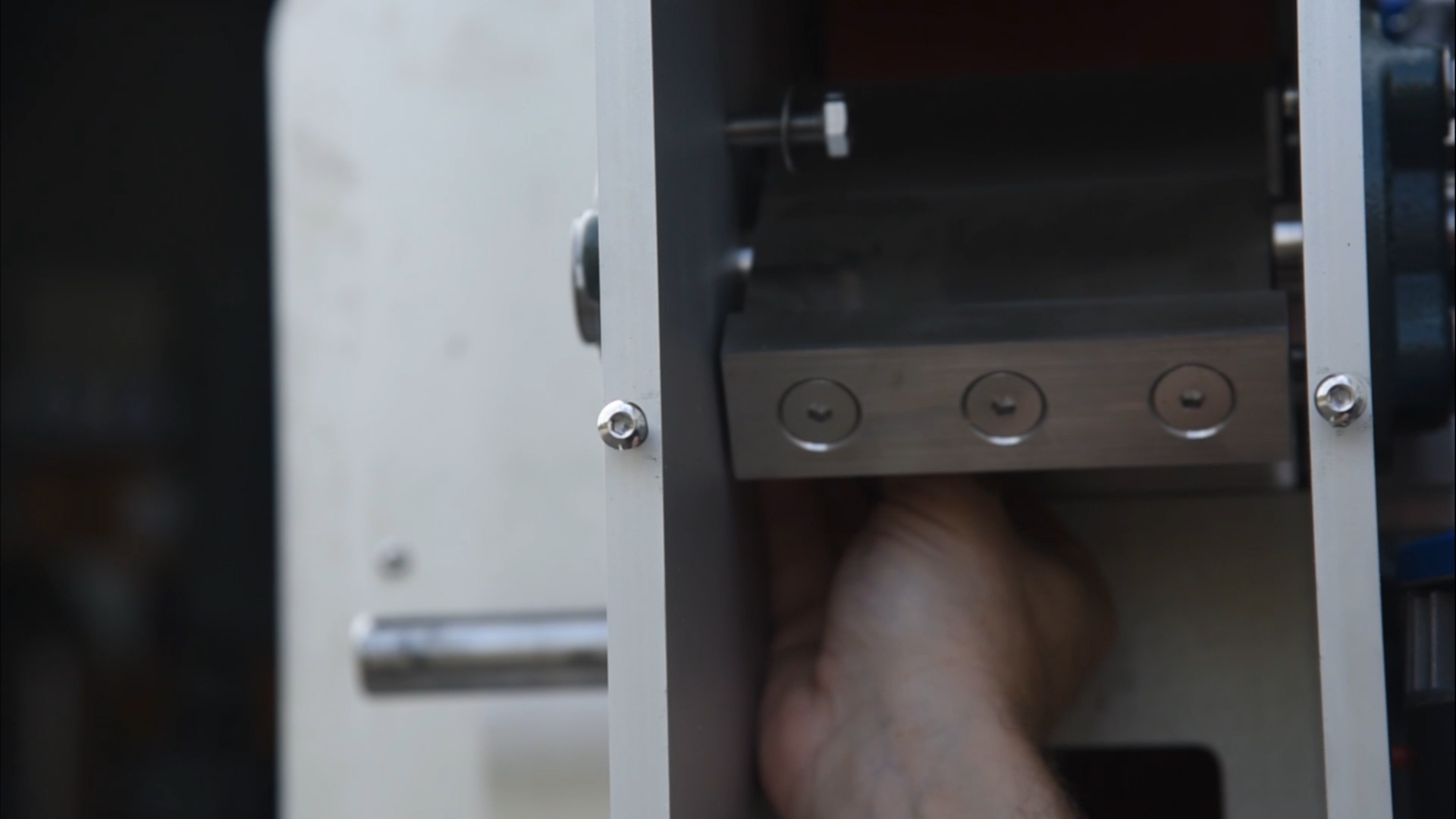
The flange should pull right off, but if it doesn’t, rotate it about 45 degrees so that the holes don’t line up anymore, then take 2 of the 4 bolts you removed and insert on the opposite side of the plate kitty-corner to each other.
10
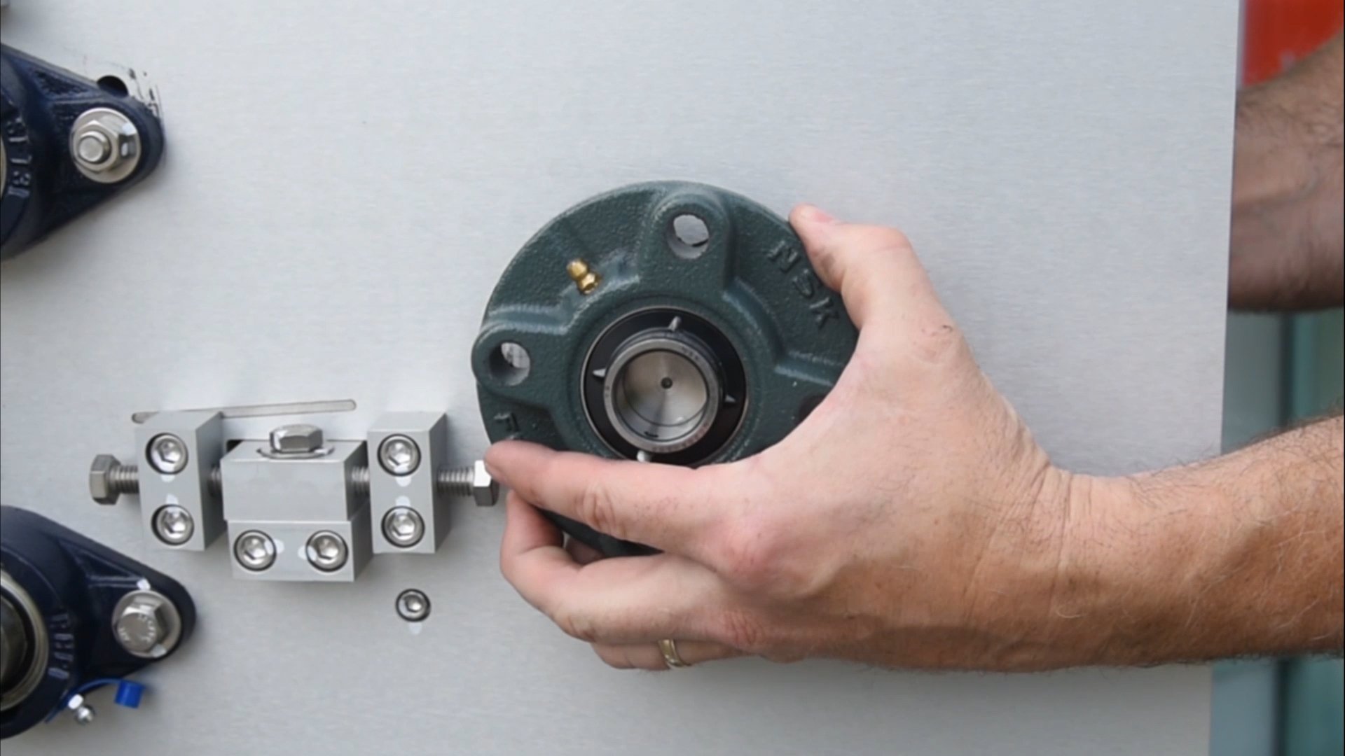
This will help push the bearing block out. Remove those bolts before moving on.
11
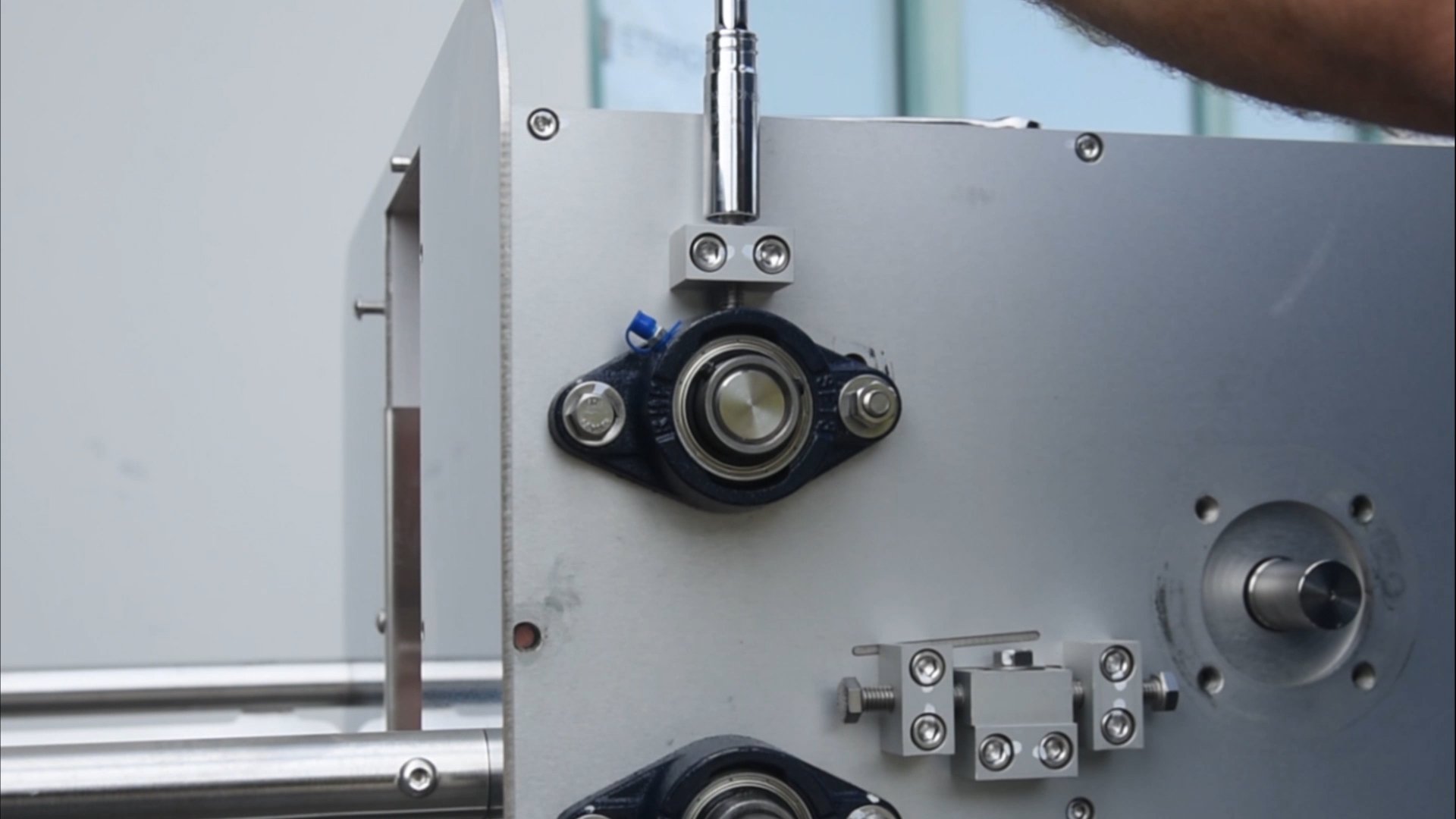
Release the tension off the rolls by loosening the top bolts on the upper 2-bolt flange bearings on both sides of the machine, then loosen the flange bolts on either side.
12
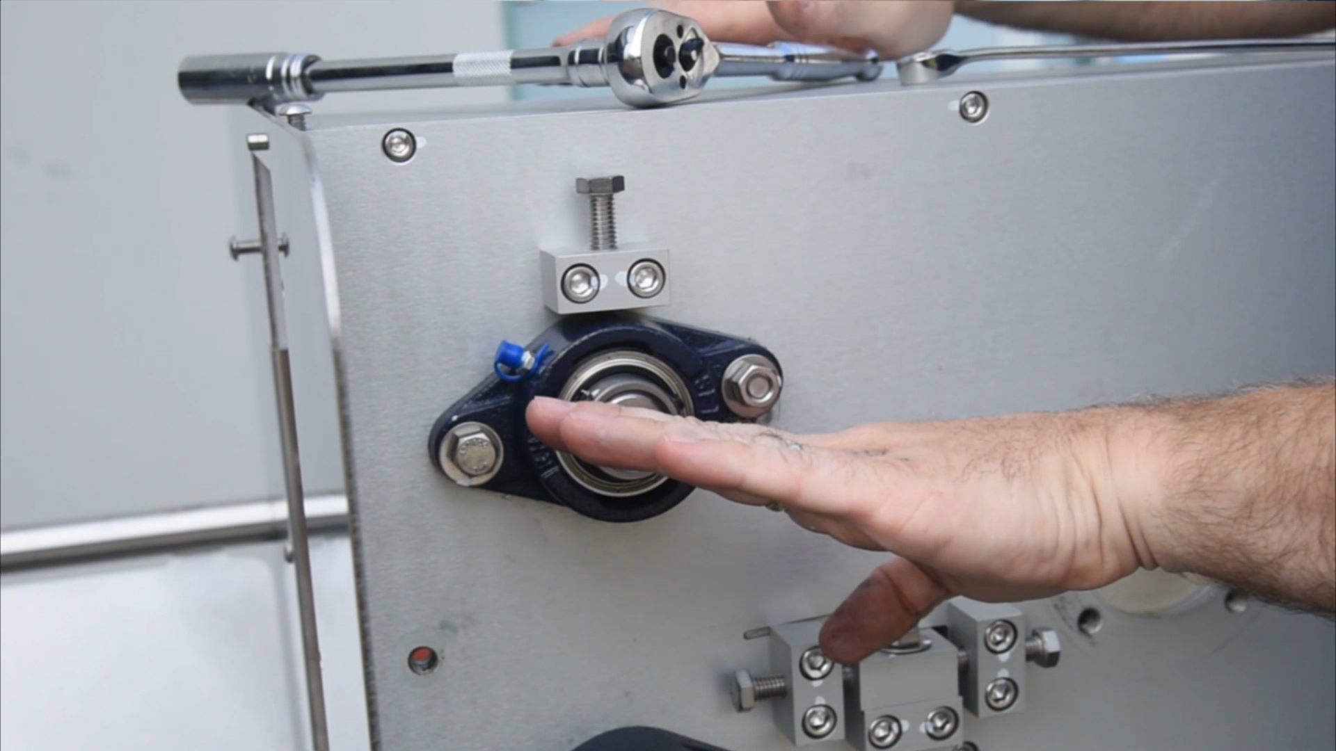
Once loose, the tension is off the rollers and the flange will float up. They pivot down to tighten and pivot up when they’re loose.
13
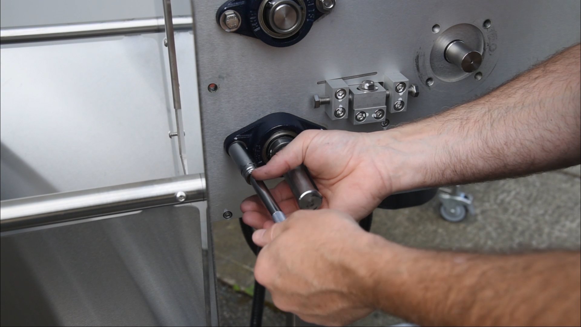
Next remove the lower flange bearing. There are 2 little plastic bushings inside the bearing – be careful not to lose those as you pull the flange off. Set the bearing off to the side.
14
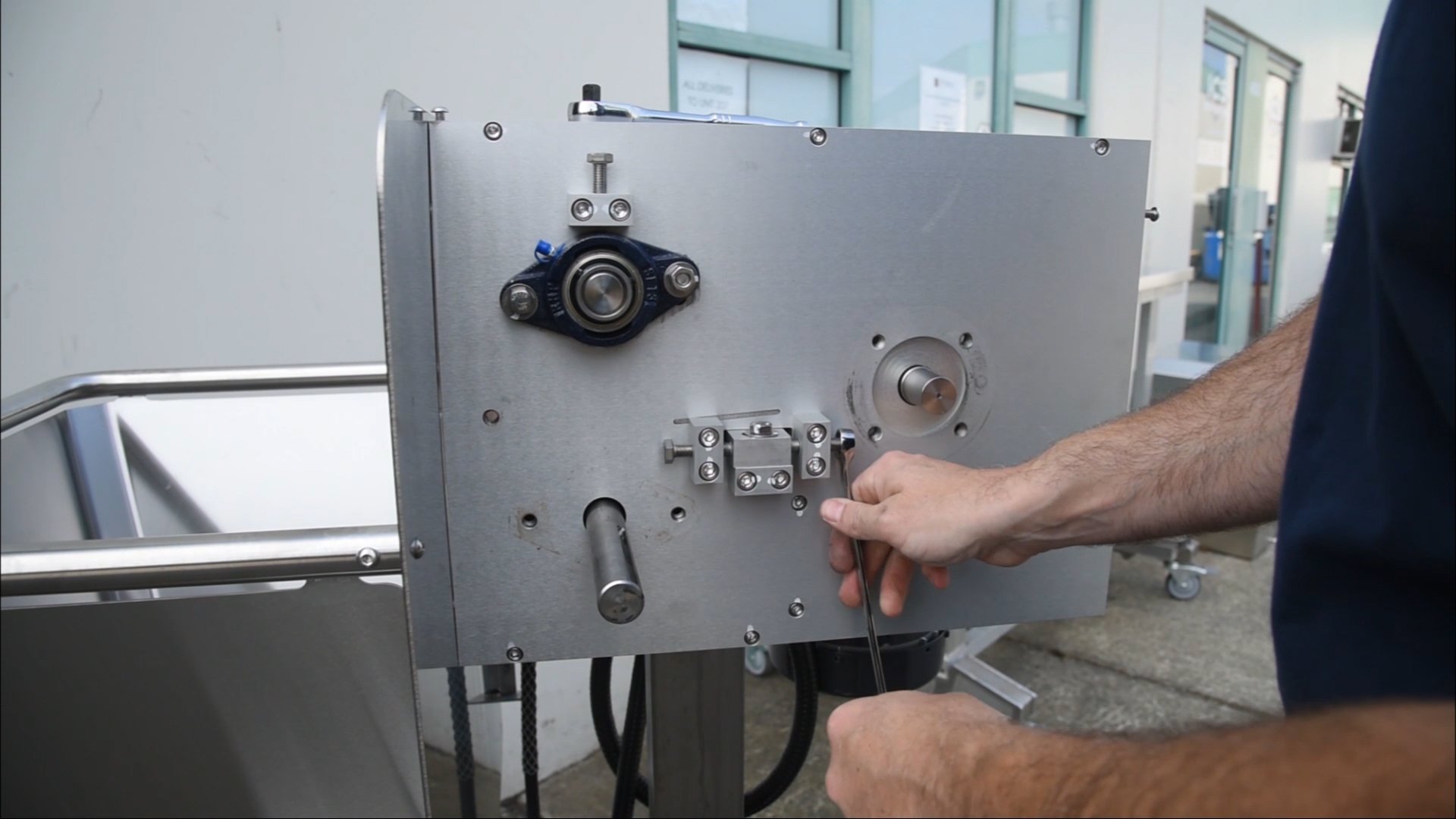
Loosen off the two adjustment bolts so there is a gap between the bolt and the blade block.
15
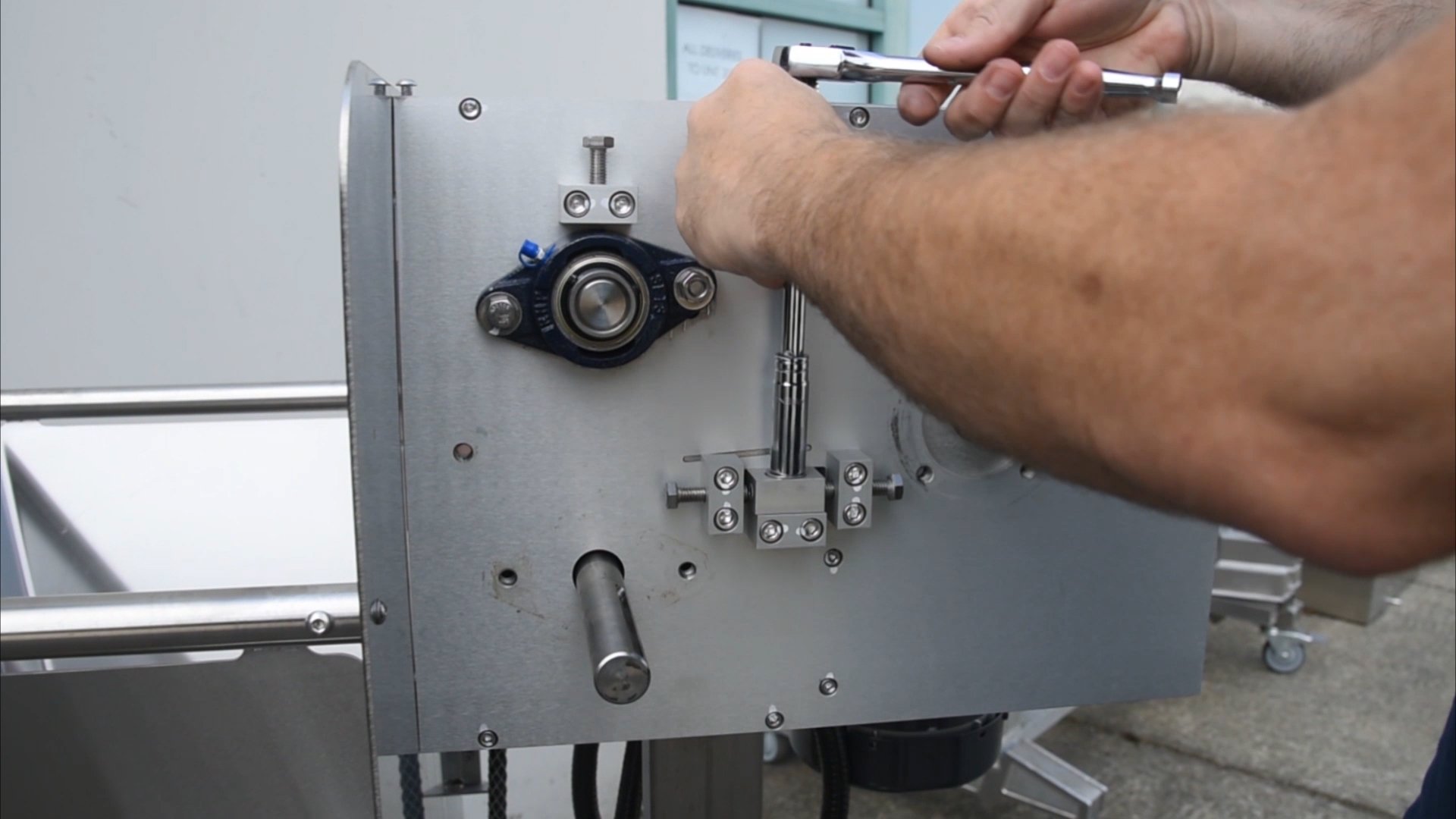
The reason for removing this portion – the adjuster bolt body – is because there is a deflector plate in behind, which will be easier to slide back in with that portion out of the way.
16
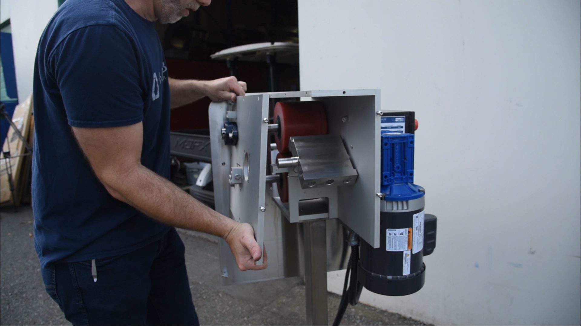
Remove the 7 bolts with the 3/16" allen wrench then remove the side plate.
17
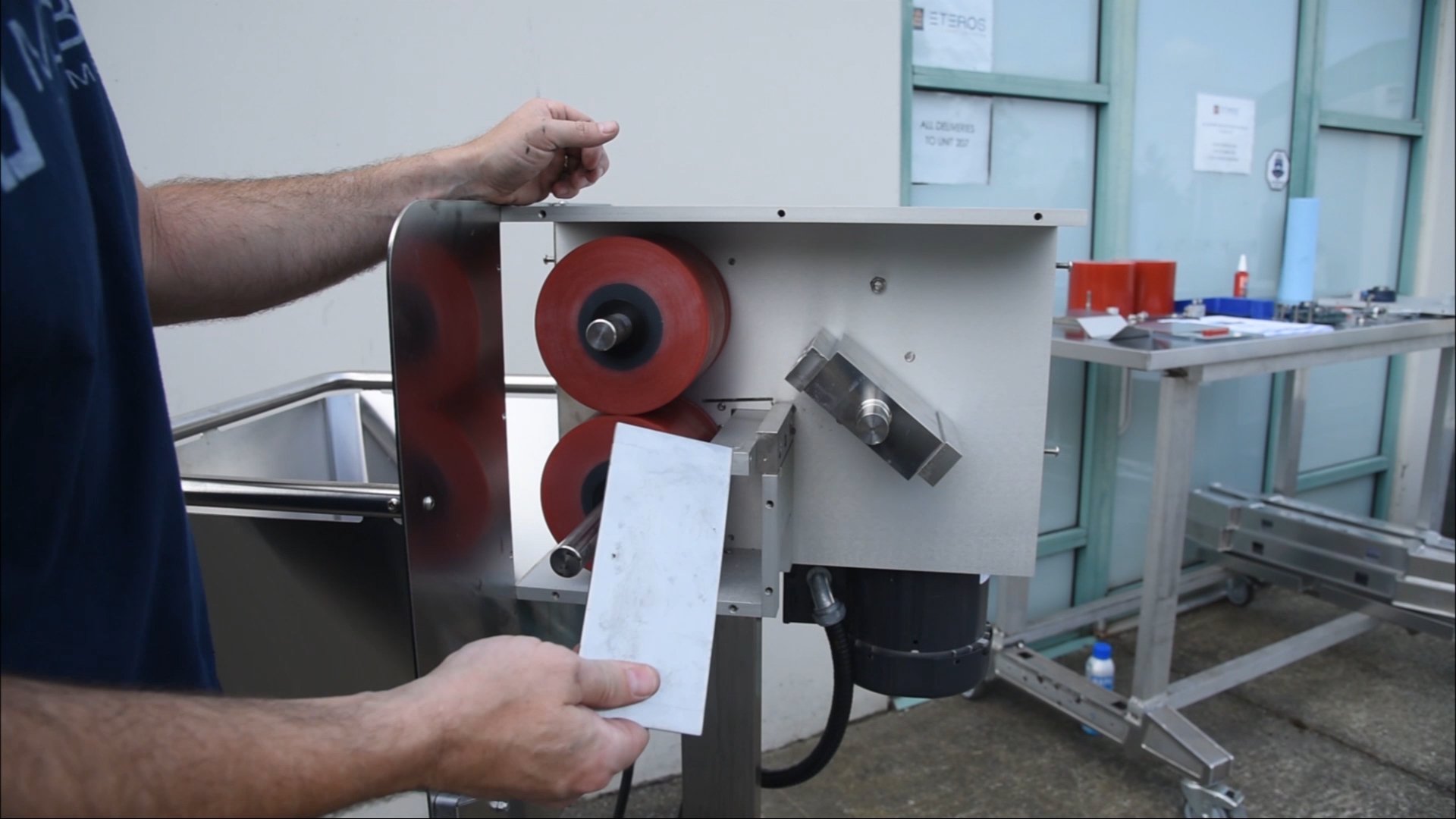
Inside you’ll see the 2 rolls and the deflector plate which you can remove now, as well as two black spacer washers.
18
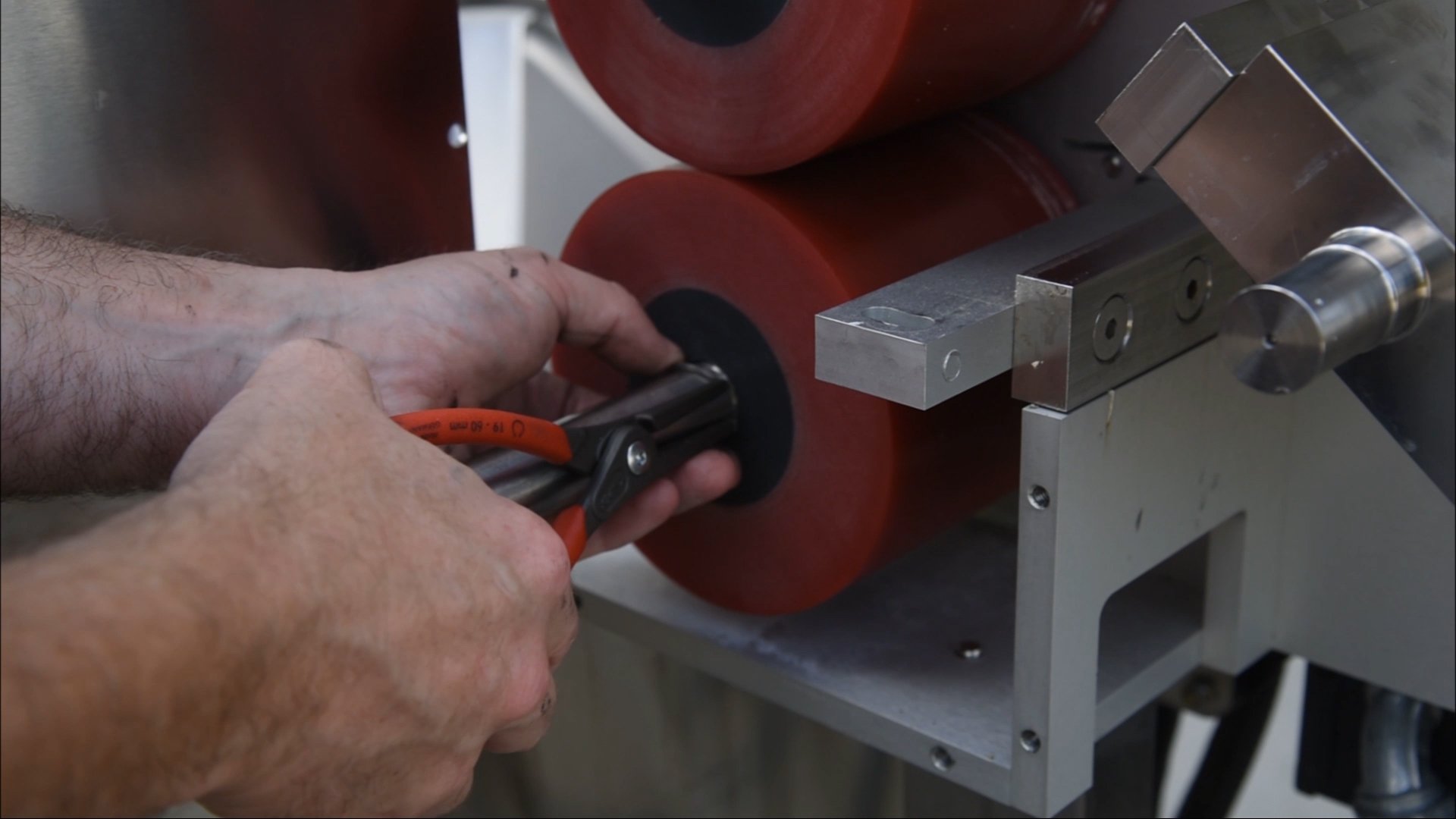
Using the circlip pliers, remove the circlip around each roller. It’s advisable to wear safety glasses during this portion as the circlips can spring off and cause injury.
19
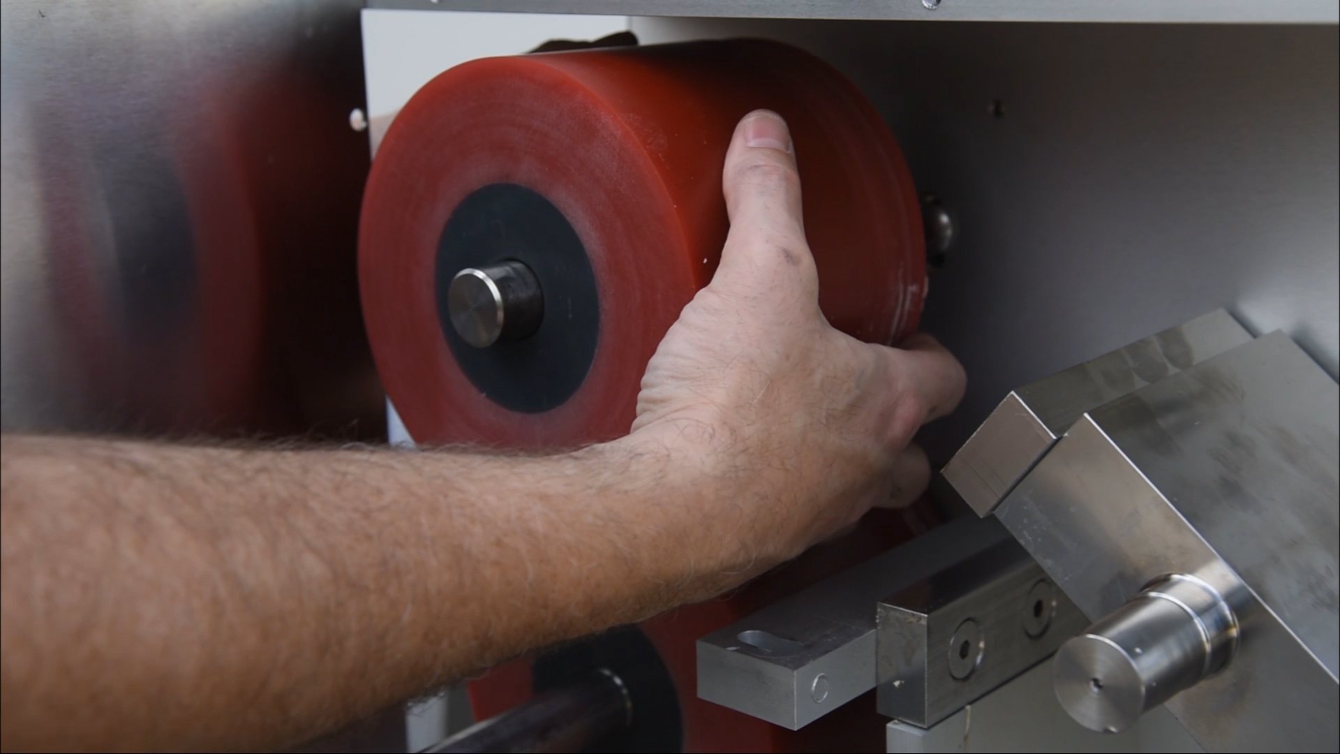
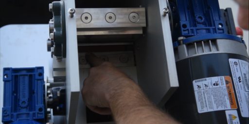
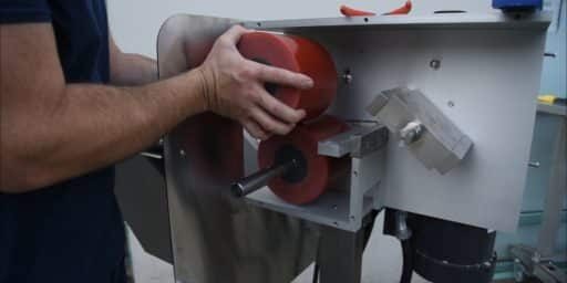
You can now remove both of the rolls. If the bottom roll is difficult to remove, use the prybar or wedge to work the roller off without damaging any of the aluminum plates, then pull it off the rest of the way.
20
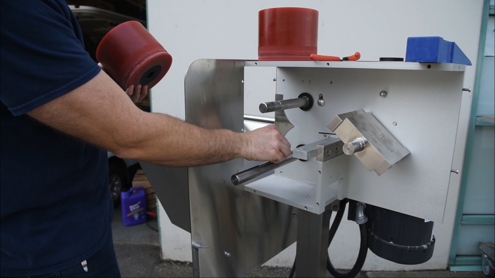
Be careful not to lose the key. This is also a good time to give the machine a thorough cleaning.
Installing The Rollers
21
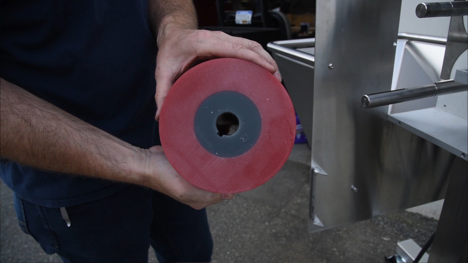
The bottom roller has a keyway. Line that up with the key and slide the roller on.
22
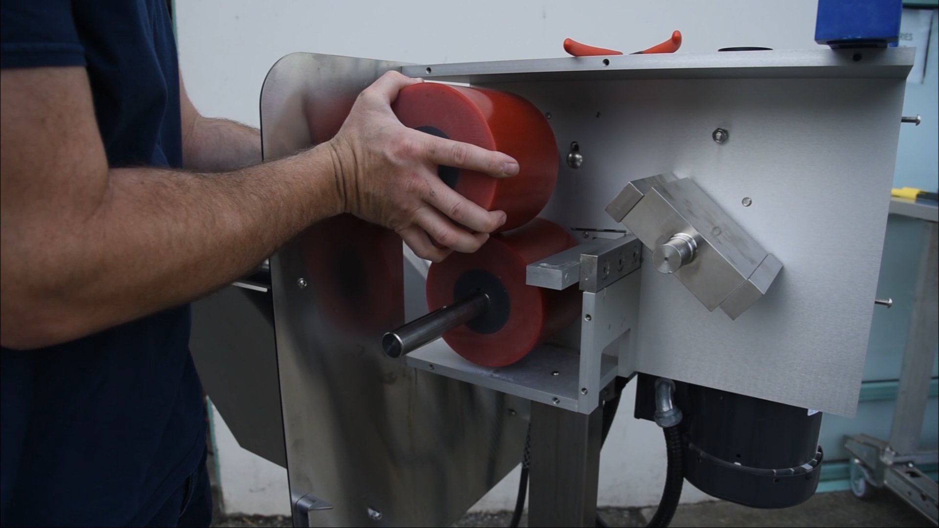
The top roller has no keyway.
23
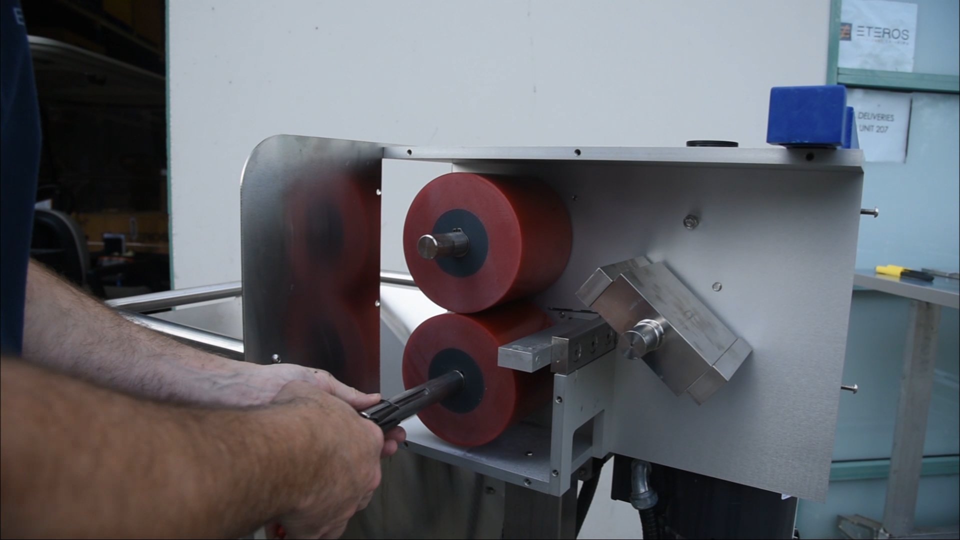
Once both are installed, with safety glasses on, put the circlips back on making sure they’re seated in the groove all the way around, then slide the spacer washers back on.
24
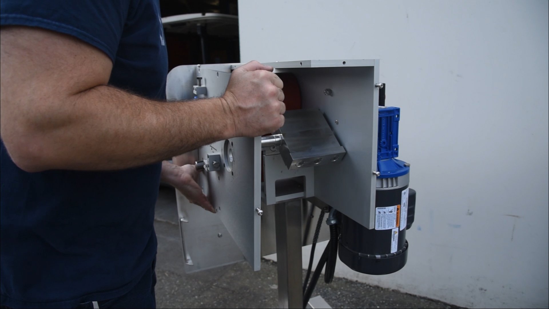
Replace the side plate making sure that all of the holes and two shafts line up properly. The top bearing will need to be moved up to line up with the shaft. Once aligned, the plate can be pushed on the rest of the way.
25
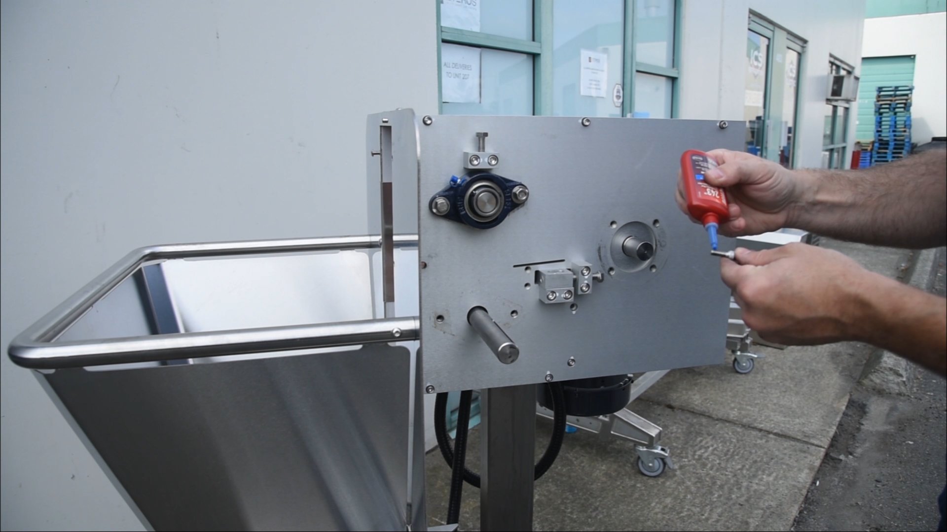
Using blue loctite, replace all seven of the screws on the side plate. Get them all started, but don’t tighten until all seven are in place. You can then go back over each and snug them all down, then go back a third time to tighten them.
26
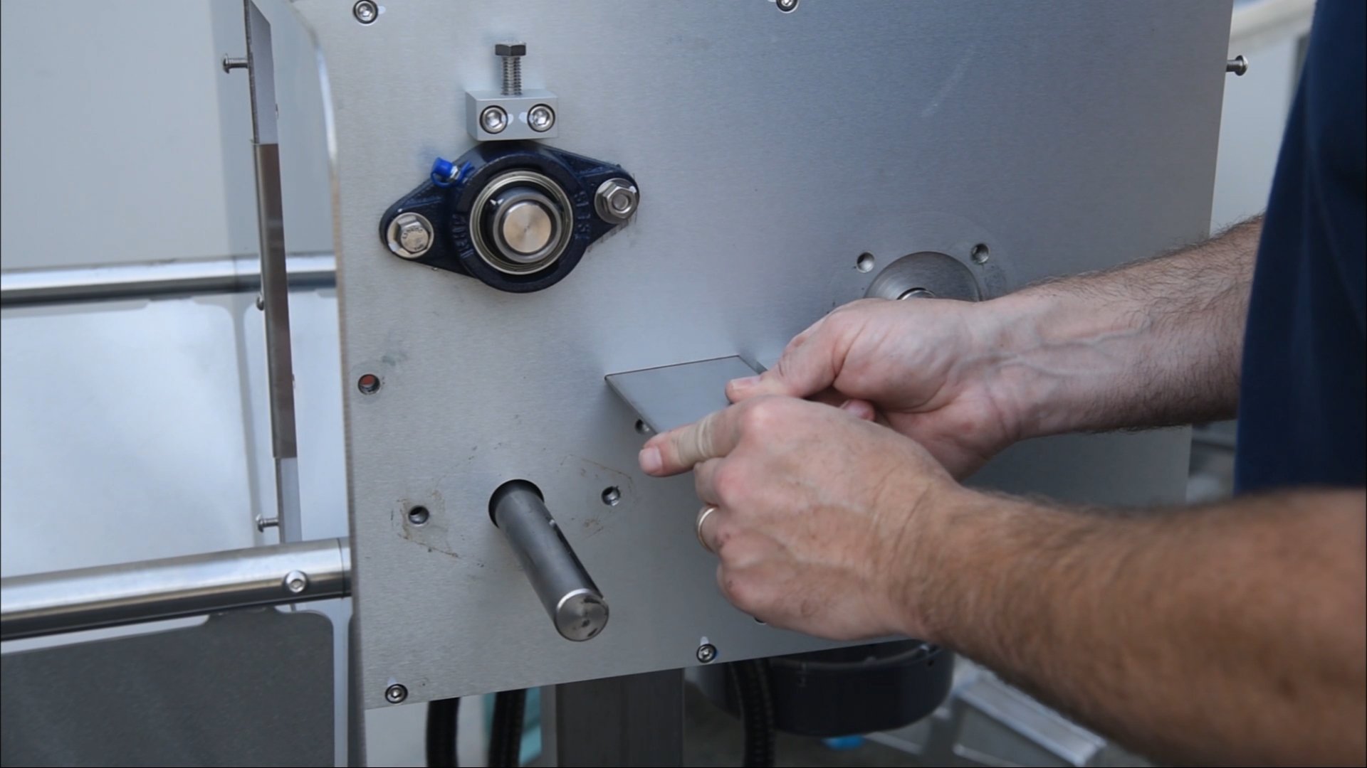
Make sure the deflector plate is very clean as it’s a tight fit. The plate should slide in easily but you may need to use a mallet to knock it in until it seats on the other side.
27
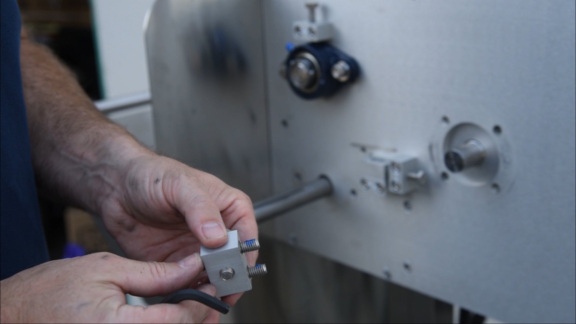
After putting blue loctite on the two bolts on the adjuster bolt body, reinstall this component by screwing both bolts in lightly, then going back and tightening them up.
28
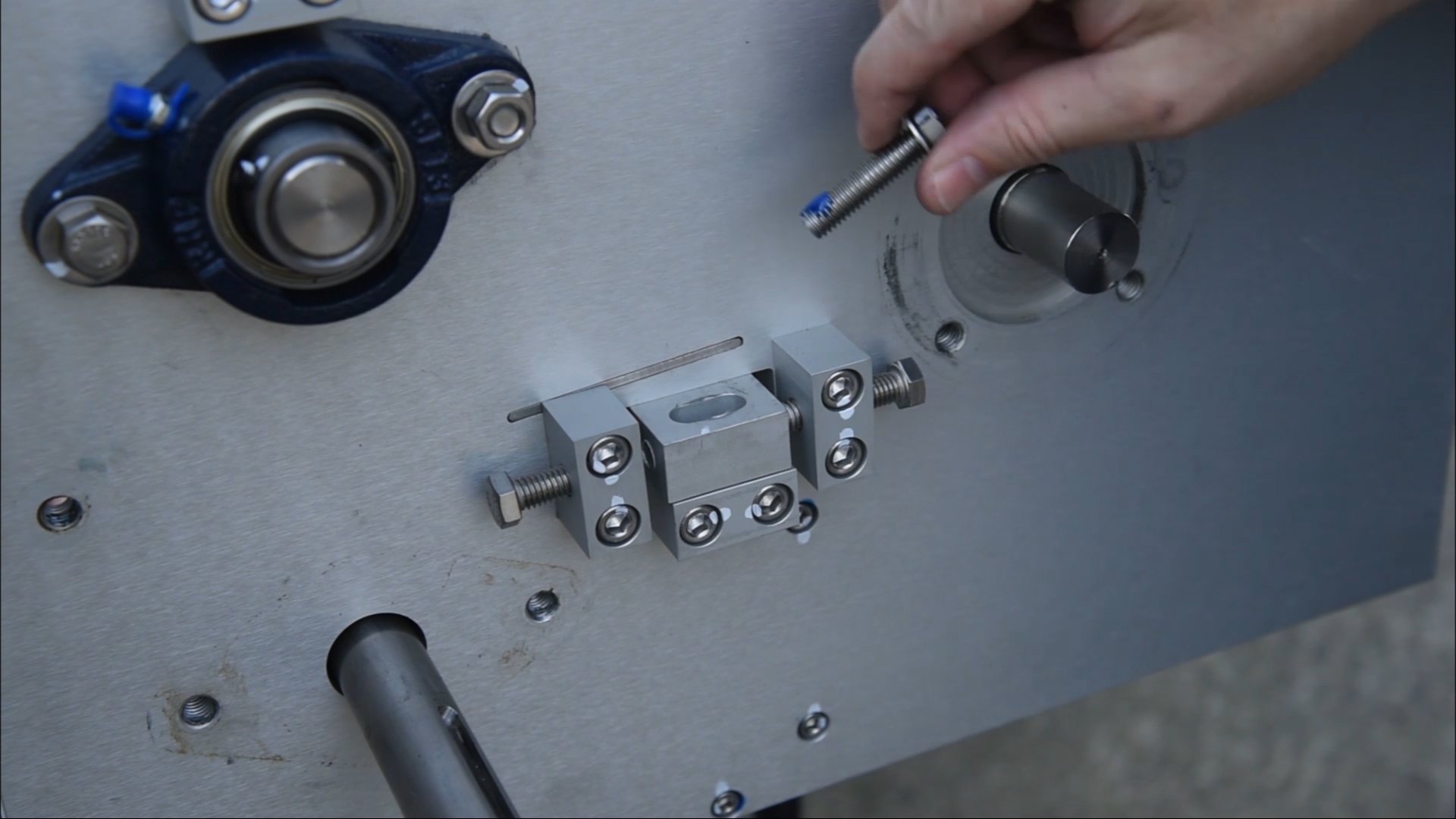
Put a bit of blue loctite on the first few threads of the bolt that goes in the top of the adjuster bolt body, and get it started by hand, being careful not to cross-thread it, then tighten it up with the wrench – not too tight, just snug.
29
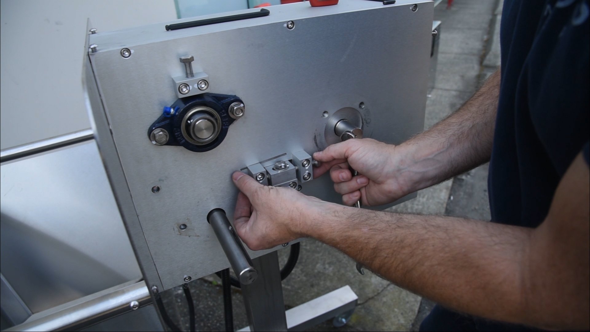
Then tighten the bolts on either side – as tight as you can with your fingers. Once all of the bolts are secured, we’ll come back to finish the chipper blade assembly.
30
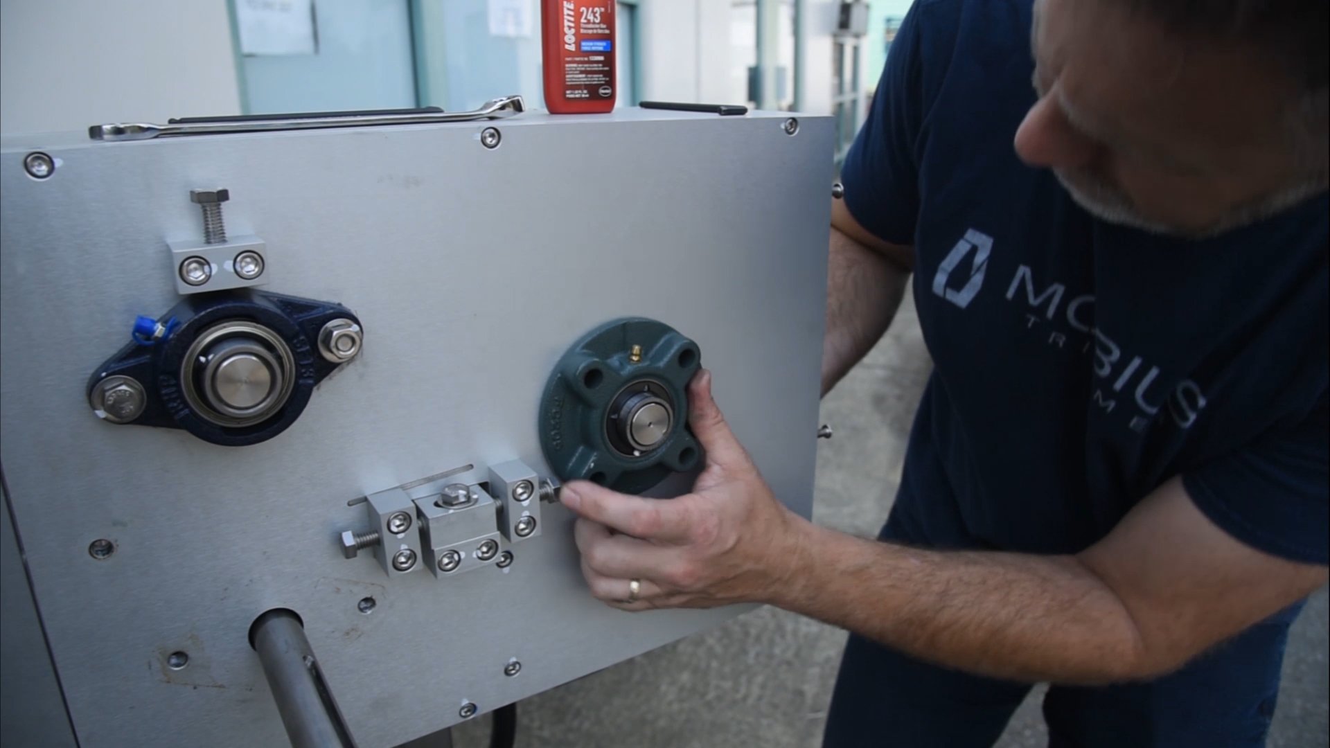
Next we’ll reinstall the 4-bolt flange bearing. Make sure the grease fitting is at the top. You may need to grab the chipper from behind and lift it to get the flange bearing to fit into its recess, then line up the 4 holes, add loctite to the first few threads and replace the 4 bolts, tightening each once they’ve all been installed.
31
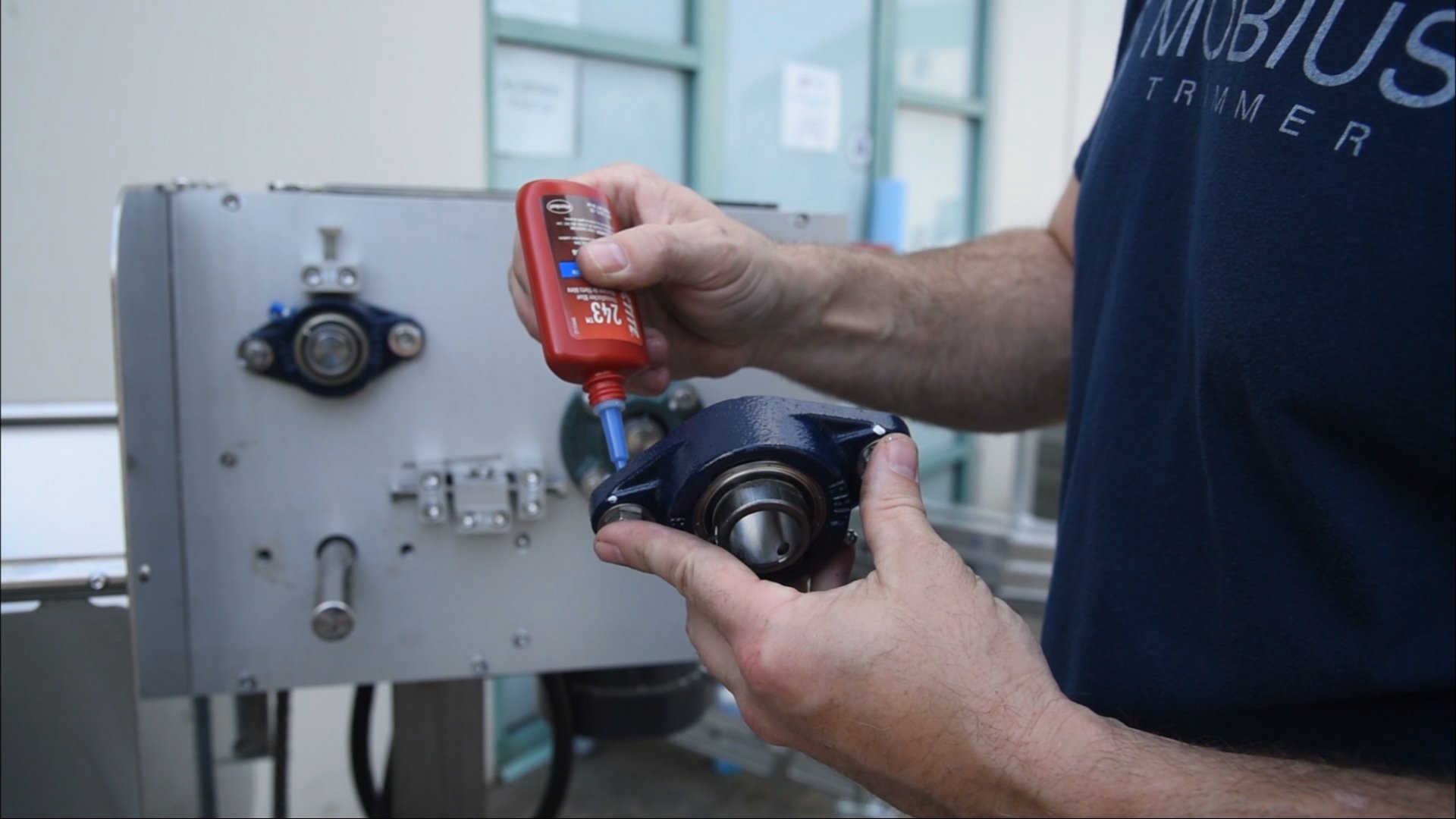
Make sure that the plastic bushings are installed in the 2 bolt lower flange bearing. Add loctite to the two bolts, then slide the bearing onto the shaft.
32

Tighten one of the bolts by hand, then pivot the other side up slightly to get that bolt started, then slide the bearing tight against the plate. Continue to thread the bolts by hand, then tighten with the socket.
33
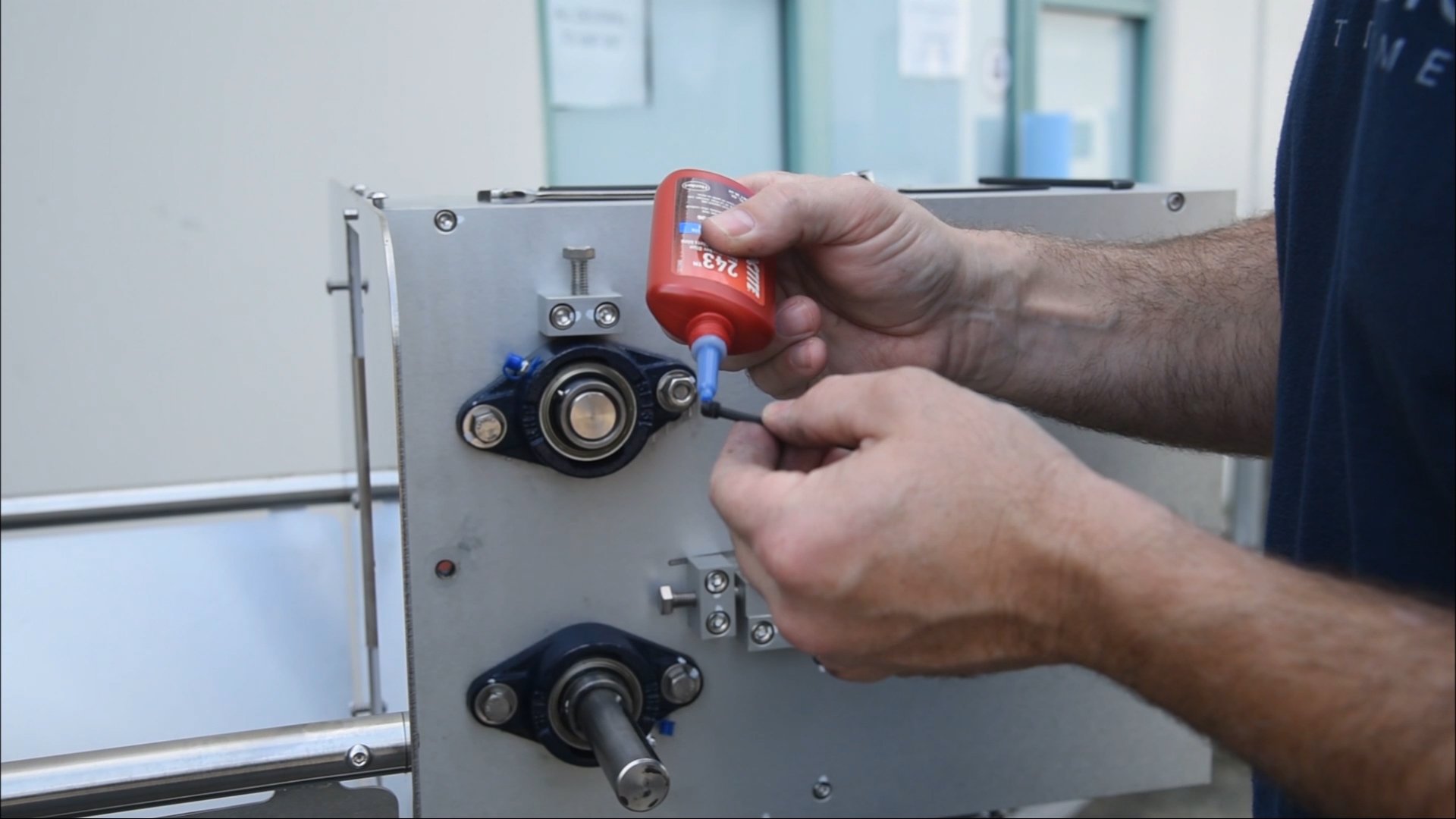
With all the flange bearings installed, you want to remove each of the 6 set screws (2 in each bearing), add a bit of blue loctite, then reinstall them using the 1/8" hex wrench. The 4-bolt flange bearing uses the 3/32" hex wrench.
34
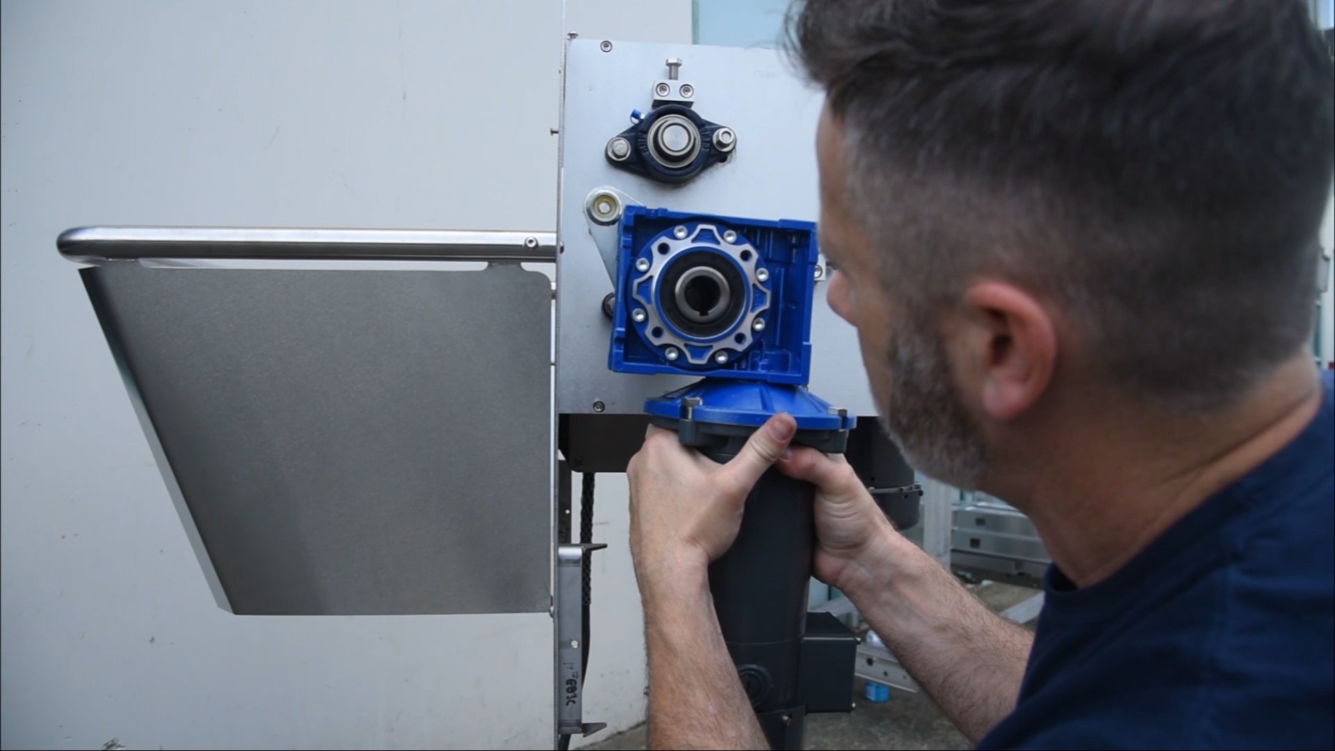
Turn the shaft of the lower flange so that it aligns with the key way on the motor gearbox. With the gearbox on about 1/2 an inch of the shaft, take the key and hold it in the key way.
35
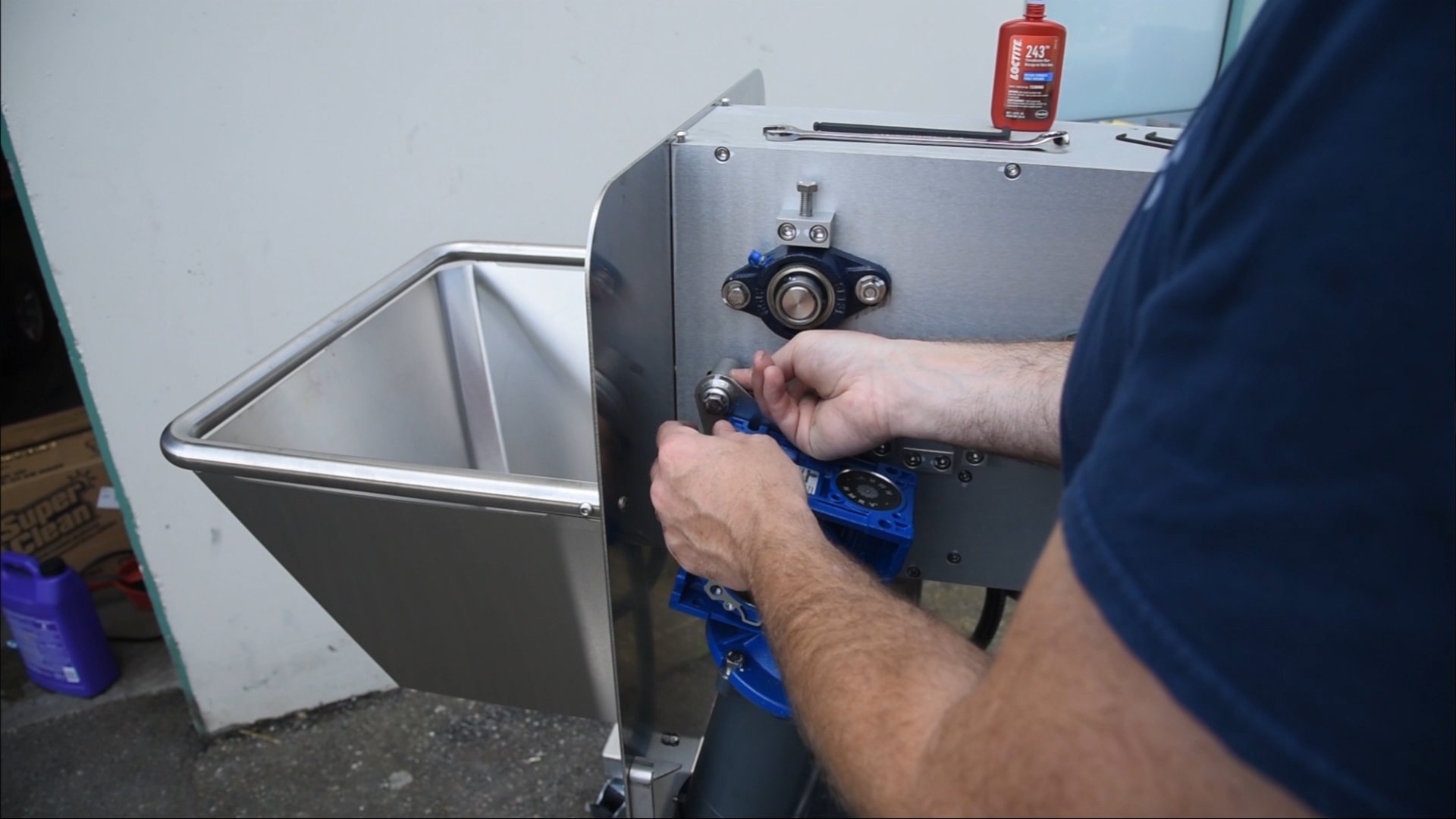
Look down the hole of the gearbox to make sure everything is lined up, then slide the whole assembly on, but leave room to install the rest of the hardware. With a bit of loctite on the bolt, pass it through the bracket and the spacer, then roll the motor until the bolt lines up with the hole in the side plate and start tightening the bolt by hand to ensure it doesn’t get cross-threaded, then tighten the rest of the way with the socket.
36
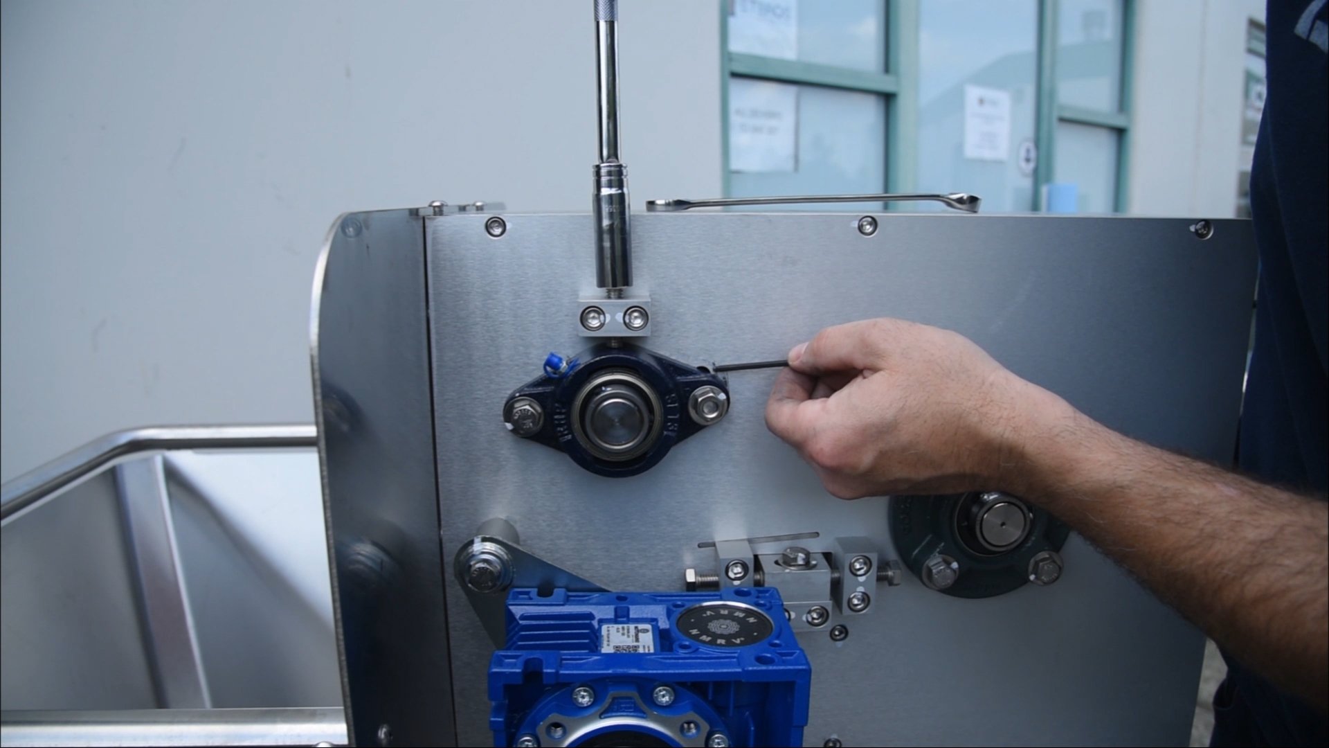
Start tightening the adjuster bolts on the top of each of the upper roll bearing blocks with the 9/16" socket. As you tighten the bolts, it will start to expose a slot where the bolt goes through. You want to tighten the bolt until you can fit a 1/8" hex key in the opening. That’s when you know the rolls are adjusted correctly. Repeat the same process on the opposite side.
37
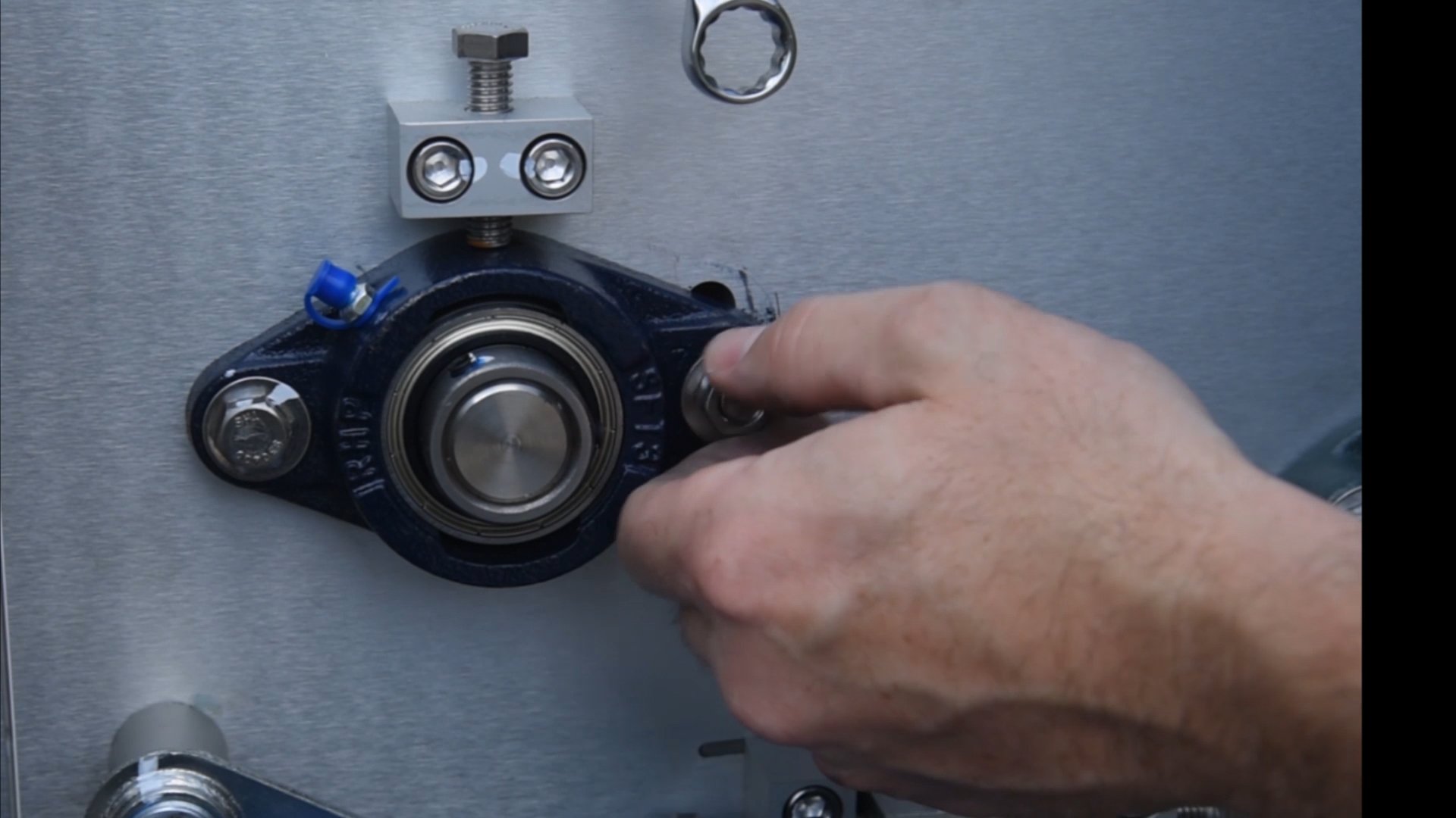
Tighten the bolts on each side of the bearing on both sides of the machine, then snug down the top bolt which will prevent the bearing block from vibrating and coming loose.
38
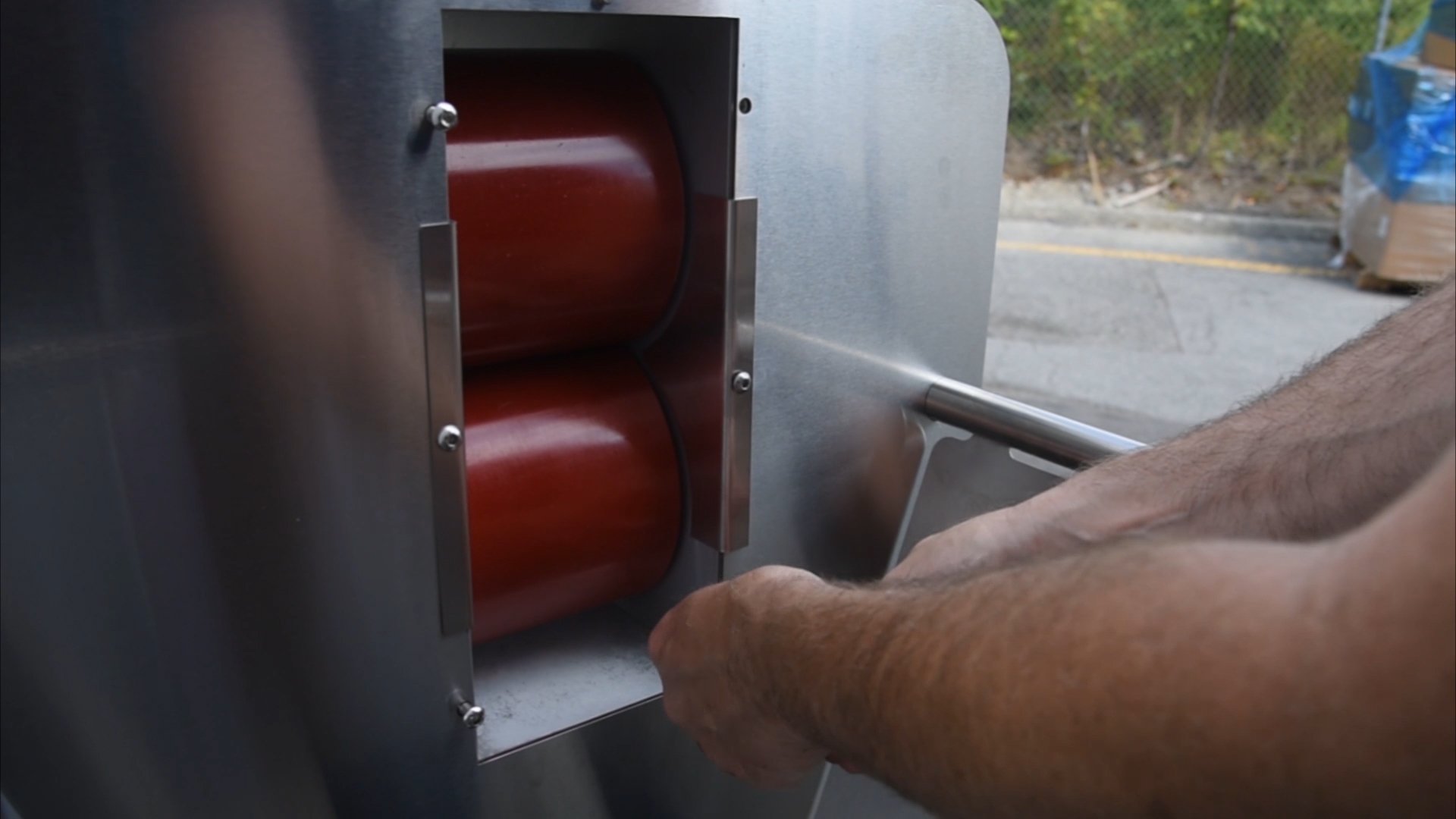
Replace the plate on the side of the rollers with the short screw. The 2 longer screws hold the dieplate in place – they can just be threaded loosely for now, but the middle screw can be tightened up.
